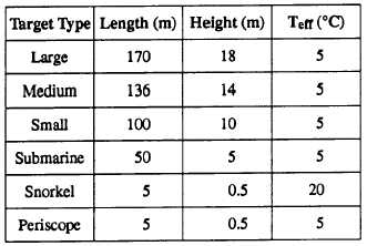
Table 7-4.-Effective Target Values
submarine-generated wake. Table 7-4 lists effective
target values used by the FLIR program.
The effective dimensions produce more realistic
ranges than use of actual target dimensions.
l An airborne FLIR sensor is viewing targets well
inside the horizon against an essentially blackbody sea.
That is, the FLIR program does not account for changes
in viewing angle resulting in a new target background
and thus a new Teff.
. If the relative humidity calculated from the input
dewpoint depression is <35 percent, then a minimum
value of 35 percent relative humidity is used only to
calculate the aerosol extinction. Design of the model
prevents accurate aerosol extinction calculations below
35 percent relative humidity.
. All environmental data from the AEF must be
quality controlled. Bad atmospheric data will produce
unreliable results.
If -1 is entered for an unknown surface visibility,
the aerosol extinction coefficient is calculated with a
visibility computed from the atmospheric sounding.
The calculated visibility is displayed on output;
however, it may or may not be similar to visibility
conditions observed. The computed visibility is a
limited approximation of the true visibility.
If -1 is entered for unknown surface wind speed,
the global average wind speed of 6.9 meters per second
(about 14 knots) is used for calculations. Actual wind
speeds lower than the global average generally yield
longer ranges. Actual wind speeds higher than the
global average will generally yield shorter ranges.
The FLIR program does not calculate ranges at
altitudes greater than the maximum height of the
sounding, This limits the height of the FLIR sensor to
the top of the meteorological data.
FUNCTIONAL DESCRIPTION
Fifty percent FLIR detection ranges are output for
predefine altitudes and target types in tabular form
based on the FLIR device selected. The 50 percent
detection range curve is also depicted graphically for
each of the target types. Output from this program is
classified and should be labeled as required
AIRCRAFT ICING (AIRICE)
LEARNING OBJECTIVES: Interpret AIRICE
displays for potential aircraft icing vs. pressure
levels. Identify limitations and assumptions.
The AIRICE program analyzes radiosonde data
from the AEF for potential ice accumulation on aircraft.
AIRICE checks each radiosonde level for potential icing
starting from the lifting condensation level (LCL). If
ice accumulation is possible, then the icing type and
intensity are determined.
The icing analysis (icing
probability, type, and intensity) is displayed in tabular
form along with radiosonde analysis data.
APPLICATION
The accumulation of ice on the exterior surfaces of
aircraft has the potential of causing serious handling
problems and can lead to a crash. Ice accretion also
increases the weight of the aircraft and reduces its
payload capacity and fuel efficiency. ‘The main cause of
aircraft ice accretion is freezing cloud droplets. The
purpose of this function is to provide an aircraft icing
assessment from which a naval forecaster can predict
flight levels where hazardous icing conditions may
occur.
LIMITATIONS AND ASSUMPTIONS
The restrictions as well as the principles taken for
granted in using the AIRICE program areas follows:
. Icing conditions are indicated at actual
radiosonde levels. The possibility of icing may exist
between the level indicated and the next higher and next
lower levels. The icing type and intensity apply to the
layer indicated, but may be valid up to the next higher
level.
7-20


