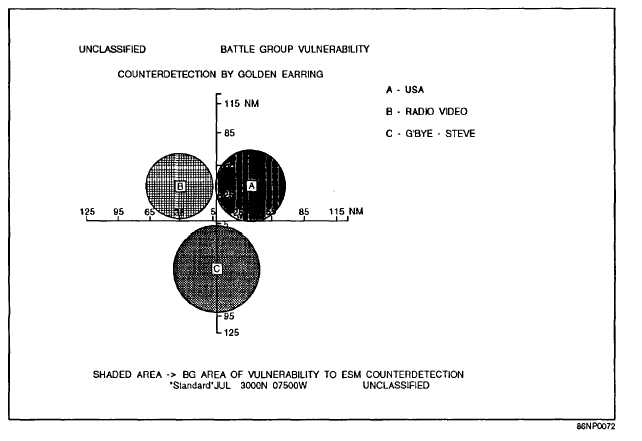
Figure 7-2.-Example output of the BGV display.
APPLICATION
The LOSS program is used to assess the
performance of a user-specified EM system under given
atmospheric conditions. Path loss vs. range is displayed
with the system’s path-loss thresholds (calculated from
the user-specified freespace ranges if not entered),
allowing the determination of maximum detection,
communication, or intercept range.
LIMITATIONS AND ASSUMPTIONS
The restrictions as well as the principles taken for
granted in using the LOSS program are as follows:
l LOSS assumes horizontal homogeneity
(horizontal changes in the refractivity structure of the
atmosphere are not accounted for).
. LOSS is valid only for EM systems with
frequencies between 100 MHz and 20 GHz.
. LOSS does not include any effects produced by
sea or land clutter in the calculation of detection or
communication ranges. This shortcoming may be
important to air-search radars in the detection of targets
flying above surface-based ducts or strong evaporation
ducts, but it is not expected to significantly affect the
predicted enhanced detection ranges within a duct.
Specifically, for surface-based ducts, the actual
detection capability at some ranges maybe reduced for
air targets flying above the duct.
. The model that calculates the LOSS display for
surface-based systems is valid only for antenna heights
between 1 and 200 m inclusive, and the program will
not accept heights outside these bounds, except in the
case of sonobuoys where the height is nominally 0.5 m.
. The airborne-loss display model does not include
sea-reflected interference effects, which could cause
both reduced and enhanced path loss for low-flying
radar or radar targets. The surface-loss display model
does not account for sea-reflected interference effects.
Only the minimum path loss within each lobe of the
interference region is plotted when the spacing between
lobes becomes very close.
. There is no account made for absorption of EM
energy from oxygen, water vapor, fog, rain, snow, or
7-5


