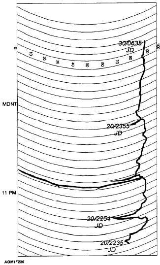
Required AN/GMQ-32 Recorder Chart
Notations
Transmissometer recorder charts (fig. 2-36) should
be set to Coordinated Universal Time (UTC); they must
have a time check with a date-time group entered at the
following times:
The beginning and end of each roll
The actual time of each synoptic hour
observation
The beginning and ending of maintenance
shutdowns or other periods when the recorder is not in
service
When you are notified of any aircraft mishap at
or near your station
Figure 2-36.—AN/GMQ-32 transmissometer recorder chart
notations.
In addition to the regular time checks with a date-
time group, other notations are required on the recorder
chart on the following occasions:
When the chart time differs by more than 5
minutes from the actual time. (Place a date-time group
on the position the pen was recording on the chart,
correct the chart time position, and enter a new date-
time group on the adjusted position.)
When a chart or any portion of the chart is
provided for any special study or investigation. (Enter
the station name, runway number, length of the
baseline, and month and year on the chart, in addition to
the required time checks.)
OA-7900A/GMQ-10
CONVERTER/INDICATOR GROUP
The OA-7900A/GMQ-10 converter/indicator
group, consisting of an ID-1939/GMQ-10 digital LED
visibility indicator and a CV-3125/GMQ-10 signal
converter (fig. 2-37), was added to most AN/GMQ-10
systems in the early 1970’s. The original ID-l939
visibility indicators used an electromechanical display
dial that was very difficult to maintain and suffered a
great deal of downtime. The display dials were
removed in the mid-1970’s and replaced with
programmable-read-only-memory (PROM) computer
chips and an LED readout for runway visual range
(RVR), in hundreds of feet.
Operation
The OA7900/GMQ-10 will provide readouts for
two different visibility readings. It provides sector
visibility, in the vicinity of the runway, and runway
visual range. Operating the OA7900/GMQ-10 in
NORMAL mode yields sector visibility. Operating the
converter in DAY or NIGHT mode, and setting the
Light-setting switch to the indicated runway-lighting
intensity, activates different calculations in the memory
to yield runway visual range. No correction for
background illumination is required. Check with the air
traffic controllers to verify the runway light-intensity
setting. Runway lights are frequently operated at
setting 2 or 3, but a pilot may request that the level
(setting) be changed.
Level 1 is dimmest and 5
brightest. Ideally, the setting used is the lowest setting
that lights can be seen through any obstruction to
visibility. Study the operator’s manual NA 50-
30GMQ10-7, Operator and Maintenance Instructions
with Illustrated Parts Breakdown, OA-7900A/GMQ-
10, for further details on operating and maintaining this
system.
2-28


